Configuring Multi-input Smoke Control Symbols in Graphics
Scenario
You want to configure a graphic representing smoke control units (RTAC, AC, DAMPER, SMOKE DAMPER, DOOR, and FAN) connected via FDCIO, HTRI, or other I/O devices.
- You opened a graphic in Edit or Engineering mode.
- In the Graphic Editor, in the View tab, select the Properties and Library Browser panes.
NOTE: You will not need the Element Tree, Depth, Evaluation Editor and other panes, which you can deselect.
- In Library Browser, select the Fire_Smoke_Control_HQ_1 library.
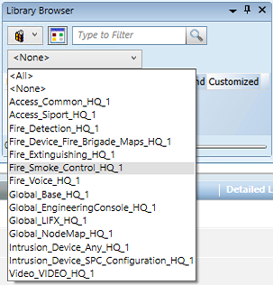
- The smoke control symbols appear in the preview area of the pane.
NOTE: Adjust the zoom factor to 90% or more to better show the symbols. Just use the slider at the bottom right of the pane.
- In the list of symbols, depending on the unit you want to represent, choose one of the following:
DYN_2D_NA_SmokeControl_AC-RTAC_None_Horizontal_001
DYN_2D_NA_SmokeControl_DAMPER_None_Horizontal_001
DYN_2D_NA_SmokeControl_DOOR_None_Horizontal_001
DYN_2D_NA_SmokeControl_FAN_None_Horizontal_001
DYN_2D_NA_SmokeControl_SMOKEDAMPER_None_Horizontal_001
STA_2D_NA_SmokeControl_AIR_None_001
STA_2D_NA_SmokeControl_LEGEND_None_Horizontal_001
NOTE: Hover over the symbol preview to display the full name as a tooltip.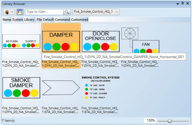
- Drag the symbol from the Library Browser into the graphic.
- The static symbol STA_2D_NA_SmokeControl_AIR… represents a flow arrow that you can select and rotate as necessary to show the air flow.
- The static symbol STA_2D_NA_SmokeControl_LEGEND… provides a legend of the status LED icons in the dynamic symbols.
- The dynamic symbols DYN_2D_NA_SmokeControl... require additional configuration actions as described in the next steps.
- In System Browser, select the Manual Navigation check box.
- Select Management View.
- In System Browser, locate and expand the fire device subtree.
- Based on the connections of the smoke control unit to devices, drag the device or input objects into the following symbol properties (in alphabetic order as displayed in the Substitution on the screen):
Object Reference: Main device applied for the smoke control functions that the symbol represents, for example a HTRI-D device. At the end of the text, after the semicolon, enter.Status.Active
Auto_Relay: Relay corresponding to the “A”, blue-colored LED
Closed_Switch: Switch input closed, corresponding to the “C”, red-colored LED; Active property = 1
Device 2 (optional): Additional device, on top of the Object Reference device. This is required to have a complete supervision when inputs are distributed on two devices.
Open_Switch: Switch input open, corresponding to the “O”, green-colored LED; Active property = 0
For example: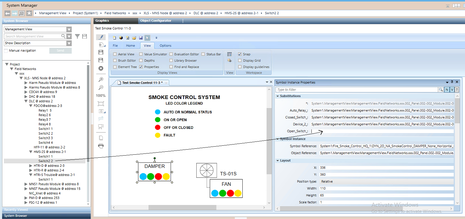
NOTE 1: The symbol for RTAC and AC units has a dual set of inputs for Return and Supply. The property labels are similar. Refer to the example below.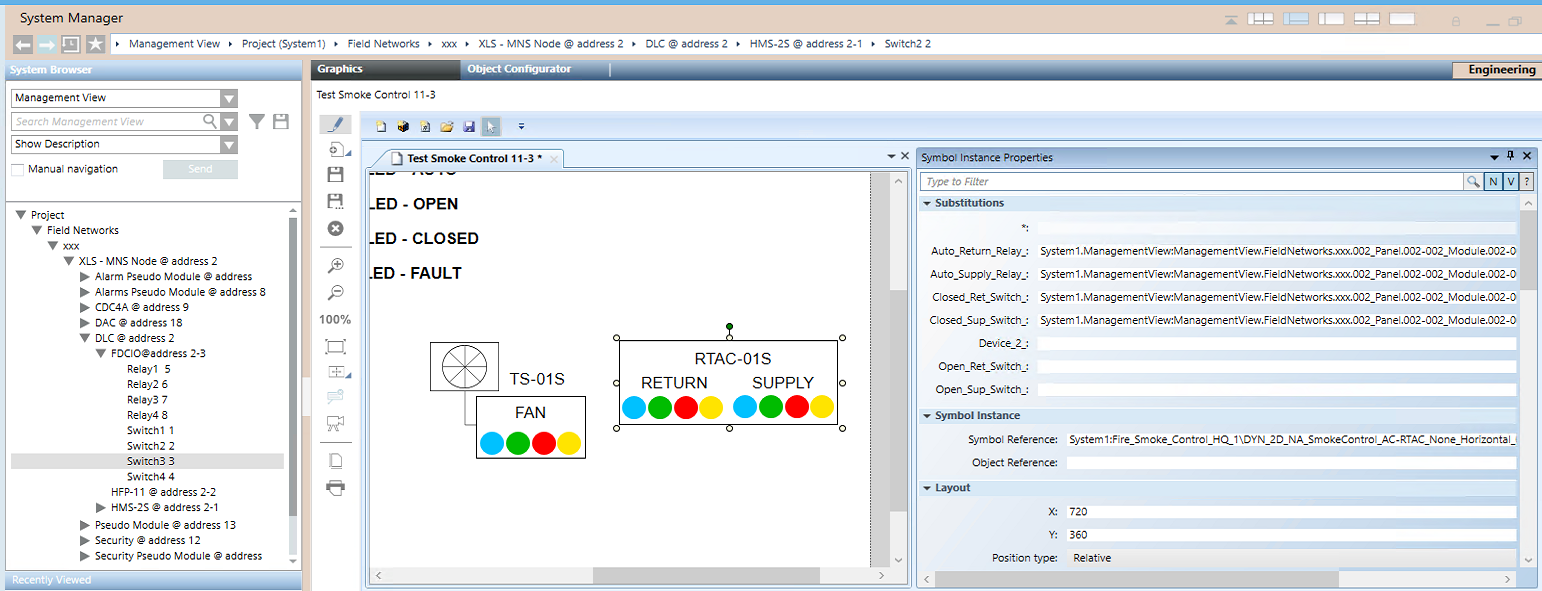
NOTE 2: In the graphic, if you need to add additional text to the symbol, use a text box and Arial font, size-16 characters, as illustrated here below.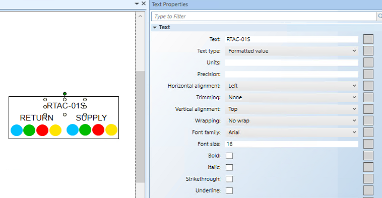
- From the Home tab of the graphic editor, add any connection lines or additional graphic elements as necessary.
- Click Save
 to save the graphic.
- Repeat this procedure to add more smoke control symbols as necessary.
- In System Browser, deselect the Manual Navigation check box.