FS92/XNET Hybrid Fire System Architectures
Desigo CC stand-alone management stations and client/server systems can combine multiple FCnet/SAFEDLINK and XNET networks in hybrid fire systems. The possible configurations are presented in the following examples.
As far as multiple FC20 and XNET connections are concerned, beyond the overall system limits, the same rules, limits, and principles apply on each connection as for the single-network architectures. See also UL/ULC Compliance: SAFEDLINK Network Limits.
NOTE: No Request/Grant/Deny (RGD) mechanism can occur to exchange control between local management stations. For each ULC-compliant fire network, the control on the fire system is assigned to the management station associated to the local control panel that has the control on the voice system.

In the following figures, the Listed PC and network devices should comply with requirements described in:
- Management Station Hardware in UL Fire Systems
- Management Station Hardware in ULC Fire Systems
- Hardware Requirements for UL Norms Compliance
- Hardware Requirements for ULC Norms Compliance

Conduits: Local connections must comply with UL 864 9th edition, and specifically to sections 49.3 exception 1 and 51.1.2 f. Copper-based wiring must be enclosed in listed conduits within 20 feet.
Stand-Alone Management Station Hybrid Fire Architecture
Single station systems can connect to both FCnet/SAFEDLINK and XNET fire networks.
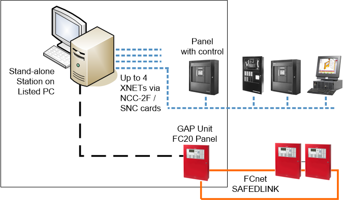
| Units installed in the same room within 20 ft from each other |
| Ethernet wiring within 20 ft in UL/ULC listed conduits |
| XNET: Style 4/Class B or Style 7/Class X RS-485 |
NOTE: Style 4/Class B = DCLB; Style 7/Class X = DCLC
Client/Server Management Station Hybrid Fire Architecture
Client/server solutions can also include both FS20 and XNET fire systems.
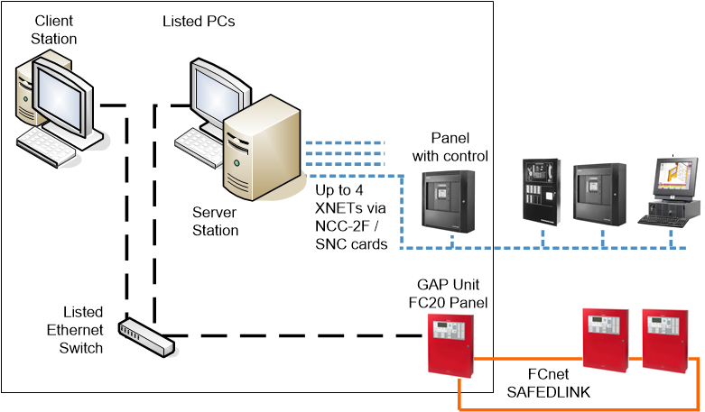
| Units installed in the same room within 20 ft from each other |
| Ethernet wiring within 20 ft in UL/ULC listed conduits |
| XNET: Style 4/Class B or Style 7/Class X RS-485 |
NOTE: Style 4/Class B = DCLB; Style 7/Class X = DCLC
Wide Client/Server Management Station Hybrid Fire Architecture with Web-based Stations
Large client/server hybrid solutions can include additional read-only web-based stations (Flex clients or Windows App clients) connected to a web server.
The remote stations can be connected to the server over fiber optic in DCLB or DCLC mode.
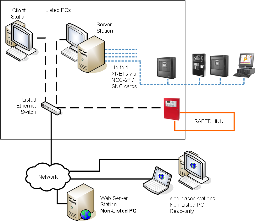
| Units installed in the same room within 20 ft from each other |
| Ethernet wiring within 20 ft in UL/ULC listed conduits |
| Ethernet over Fiber optic cable (Single mode or Multi mode), connected in Style4/ Class B or Style7/Class X |
| XNET: Style 4/Class B or Style 7/Class X RS-485 |
NOTE: Style 4/Class B = DCLB; Style 7/Class X = DCLC
Wide Client/Server Management Station Architecture with Multiple Hybrid Fire Networks and FEP Stations
Client/server solutions can also support multiple fire networks, both local and remote. A FEP station or a VNT adapter is required for an additional XNET connection, whereas multiple FCnet/SAFEDLINK can connect to the same server/FEP station up to the limits discussed in UL/ULC Compliance: SAFEDLINK Network Limits.
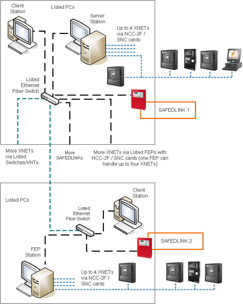
| Units installed in the same room within 20 ft from each other |
| Ethernet wiring within 20 ft in UL/ULC listed conduits |
| Ethernet over Fiber optic cable (Single mode or Multi mode), connected in Style4/ Class B or Style7/Class X |
| XNET: Style 4/Class B or Style 7/Class X RS-485 |
NOTE: Style 4/Class B = DCLB; Style 7/Class X = DCLC
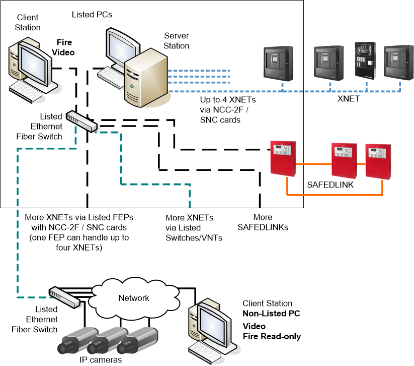
Wide Client/Server Management Station Architecture with Hybrid Fire Networks and Video
Desigo CC can support a video network connecting IP cameras along with any fire system, which can include a single network (FCnet/SAFEDLINK or XNET) or combine both types of fire networks.
The fire section of the system must comply with the UL 864 / ULC S527 requirements, whereas the video network can include any network components.
Compliant fire stations can provide for video functions. Additional client stations, which are not part of the approved system, can be added for supporting video functions. No fire control function is allowed on such stations.
| Units installed in the same room within 20 ft from each other |
| Ethernet wiring within 20 ft in UL/ULC listed conduits |
| Ethernet over Fiber optic cable (Single mode or Multi mode), connected in Style4/ Class B or Style7/Class X |
| XNET: Style 4/Class B or Style 7/Class X RS-485 |
NOTE: Style 4/Class B = DCLB; Style 7/Class X = DCLC
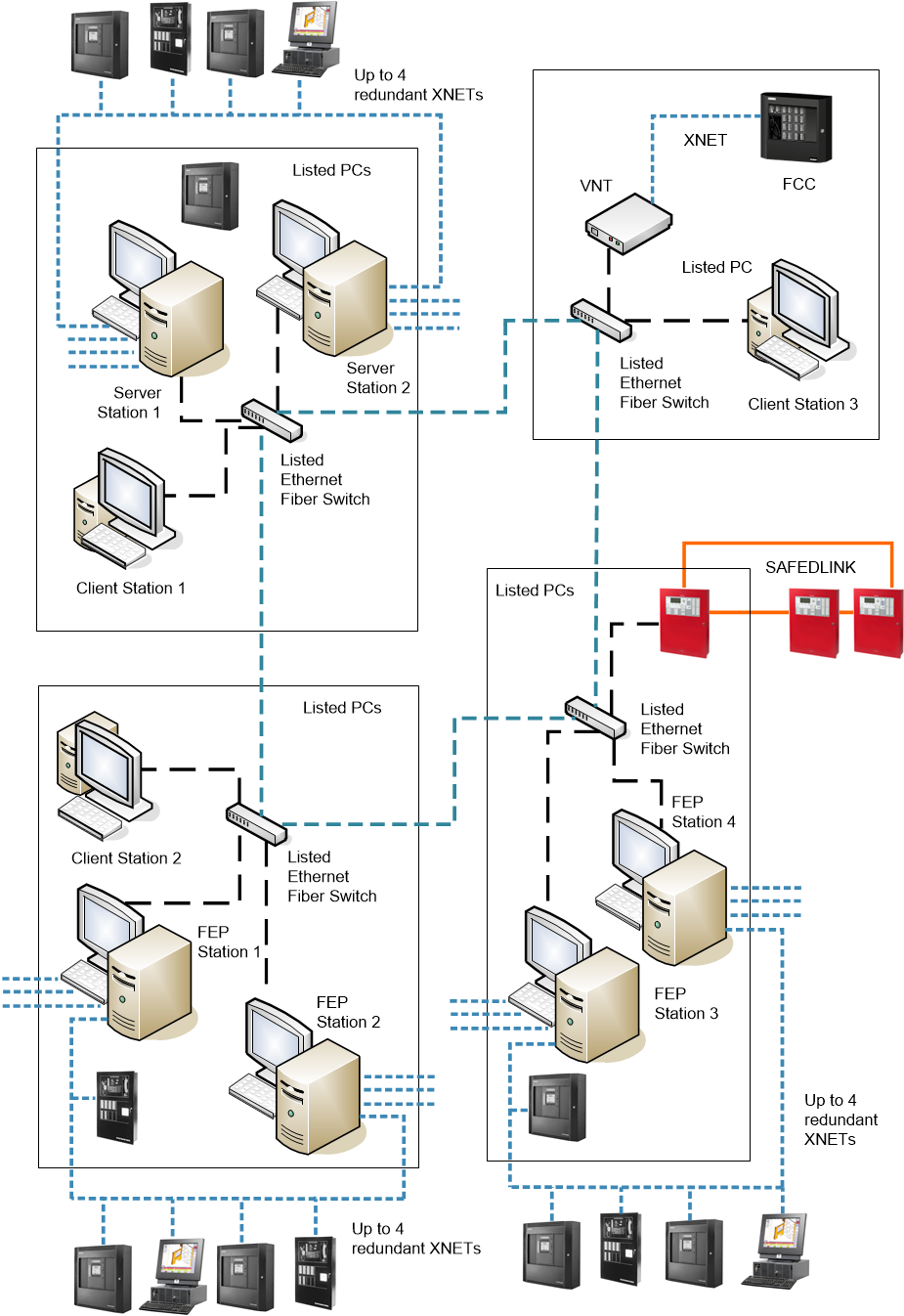
Redundant Management Station Servers and FEPs Hybrid Fire Architecture
A large hybrid client/server solution can support redundant sets of stations, including dual servers and dual FEPs. While the main system has full control, the backup system runs with no control of the fire system. If the main system fails, a manual operation on all stations (user account switchover) can transfer the control to the redundant system.
| Units installed in the same room within 20 ft from each other |
| Ethernet wiring within 20 ft in UL/ULC listed conduits |
| Ethernet over Fiber optic cable (Single mode or Multi mode), connected in Style4/ Class B or Style7/Class X |
| XNET: Style 4/Class B or Style 7/Class X RS-485 |
NOTE: Style 4/Class B = DCLB; Style 7/Class X = DCLC
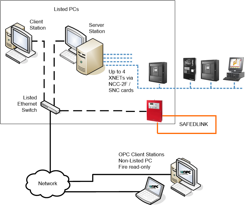
Third-party OPC Client Hybrid Fire Architecture
A fire system can also include a connection to third-party client stations over a local or remote networked link operating with OPC standard protocol. The OPC client stations cannot control the fire system and have display capabilities only.
| Units installed in the same room within 20 ft from each other |
| Ethernet wiring within 20 ft in UL/ULC listed conduits |
| Ethernet over Fiber optic cable (Single mode or Multi mode), connected in Style4/ Class B or Style7/Class X |
| XNET: Style 4/Class B or Style 7/Class X RS-485 |
NOTE: Style 4/Class B = DCLB; Style 7/Class X = DCLC
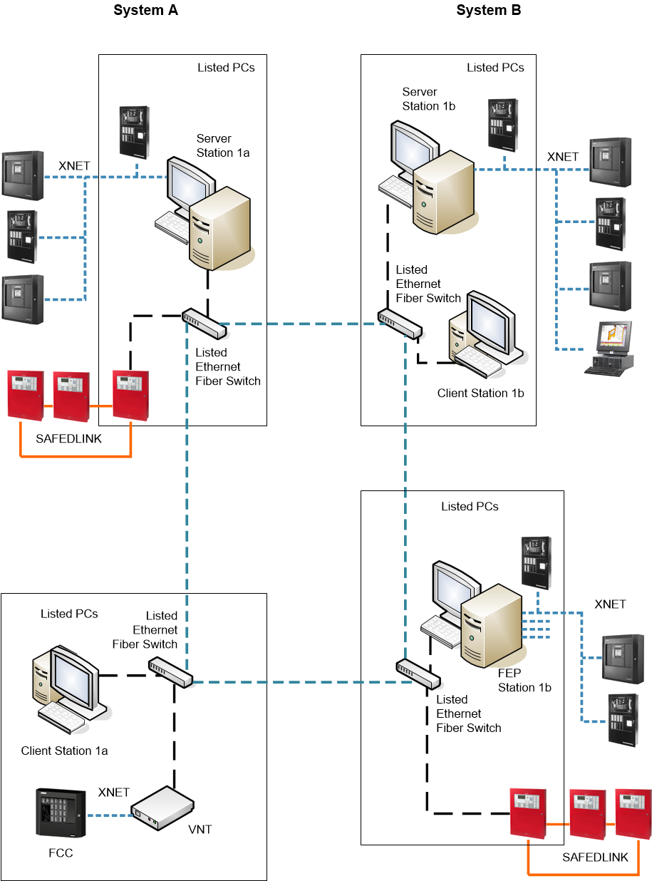
Distributed Systems Architecture with Hybrid Fire Networks
Very large-size solutions may include multiple local systems in a distributed architecture. Local systems are deployed to interconnected computers and connected to multiple fire networks. The client stations can access data from all fire networks.
| Units installed in the same room within 20 ft from each other |
| Ethernet wiring within 20 ft in UL/ULC listed conduits |
| Ethernet over Fiber optic cable (Single mode or Multi mode), connected in Style4/ Class B or Style7/Class X |
| XNET: Style 4/Class B or Style 7/Class X RS-485 |
NOTE: Style 4/Class B = DCLB; Style 7/Class X = DCLC
Distributed Systems Architecture with Redundant Fire Networks
Distributed architectures can include local systems with redundant fire networks.
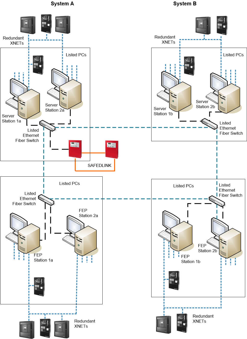
| Units installed in the same room within 20 ft from each other |
| Ethernet wiring within 20 ft in UL/ULC listed conduits |
| Ethernet over Fiber optic cable (Single mode or Multi mode), connected in Style4/ Class B or Style7/Class X |
| XNET: Style 4/Class B or Style 7/Class X RS-485 |
NOTE: Style 4/Class B = DCLB; Style 7/Class X = DCLC
Distributed Systems Architecture on a Single Server
In distributed architectures, each local system is based on a project, and projects can be deployed to one or more interconnected server computers. For example, a single server can handle 2 systems belonging to the same distributed architecture.
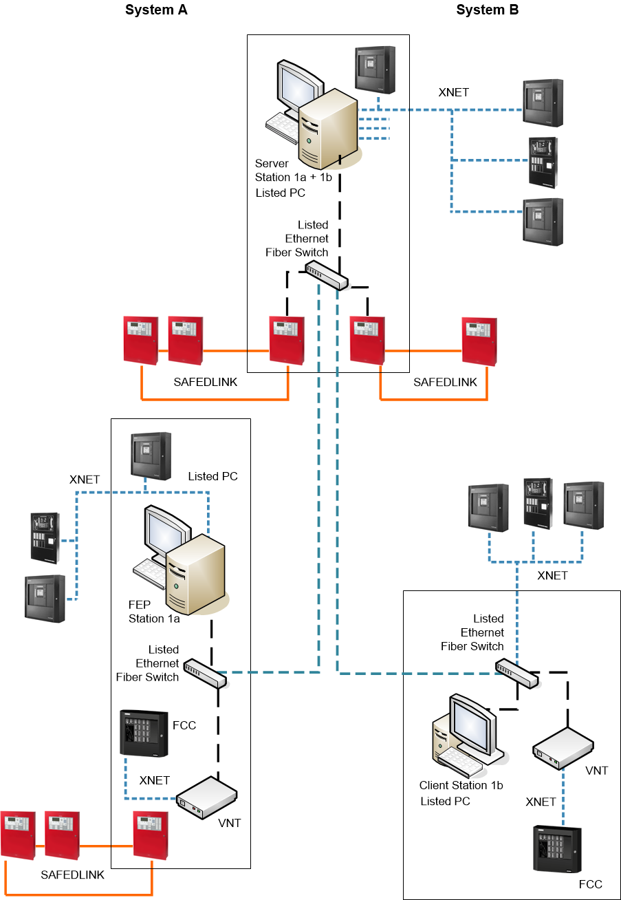
| Units installed in the same room within 20 ft from each other |
| Ethernet wiring within 20 ft in UL/ULC listed conduits |
| Ethernet over Fiber optic cable (Single mode or Multi mode), connected in Style4/ Class B or Style7/Class X |
| XNET: Style 4/Class B or Style 7/Class X RS-485 |
NOTE: Style 4/Class B = DCLB; Style 7/Class X = DCLC
Remote Desktop Access for Engineering-Only Purposes
For engineering purposes, a networked connection to a fire system is possible via Remote Desktop services. The remote computer has a read-only access to the fire networks.
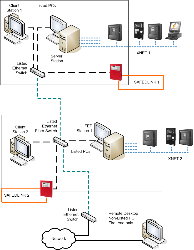
| Units installed in the same room within 20 ft from each other |
| Ethernet wiring within 20 ft in UL/ULC listed conduits |
| Ethernet over Fiber optic cable (Single mode or Multi mode), connected in Style4/ Class B or Style7/Class X |
| XNET: Style 4/Class B or Style 7/Class X RS-485 |
NOTE: Style 4/Class B = DCLB; Style 7/Class X = DCLC
Remote Desktop support is intended for troubleshooting only allowed to authorized engineer and applying network authentication.
In the Windows Remote Desktop settings, the Allow connections only from computers running Remote Desktop with Network Level Authentication option must be selected.


